General planning Guide
The following points should be taken into account:
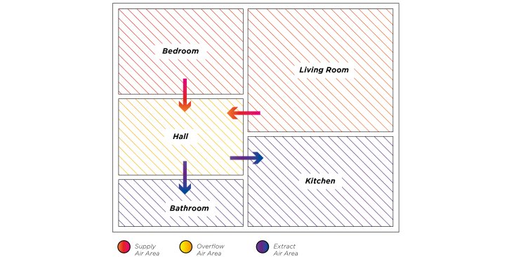
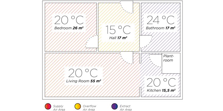
To create the specific and effective volume of airflow required for a modern hygienic building, the living areas should be divided into supply air, overflow air and extract air areas. The supply air is ducted to outlets which are installed in the window areas of living rooms and bedrooms. The extract air is drawn through the overflow air areas (hall, corridors and landings) to the high-demand areas (kitchen, bathroom and WC). For the overflow air areas air vents should be provided, acccording to DIN 1946 Part 6. Overflow air openings can be grilles, valves or door gaps with a free cross-sectional area of at least 150 cm2. For each door of the relevant room, 25 cm2 can be added to the free cross-sectional area of the overflow air opening. Between the individual areas a "room air connection" must be established.
General Design tips
The outside air supply opening should if possible be installed on the garden side (not the noise and contaminant-polluted street side) at a height of at least 3m above ground level. The exhaust air should preferably be extracted on the leeward side using a roof hood. Both openings should be arranged so that no short circuiting occurs.
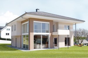
Design example single family dwelling
Calculation and design for a single family residence according to DIN 1946 – 6 of May 2009 starts with establishing the surface areas and volumes of rooms that have been divided into relevant areas. The standard internal temperatures are established according to DIN EN 12831.
Example single family residence:
Surface area: 130,50 m2
Room height: 2,50 m2
Volume: 326,25 m3
Area for supply air: 81,00 m2
Volume for supply air area: 202,50 m3
Area for overflow air: 17,00 m2
Volume for overflow air area: 42,50 m3
Area for extract air: 32,50 m2
Volume for extract air area: 81,25 m3
Fire prevention
For single-family dwellings there are no particular requirements regarding fire prevention. The ducts should be manufactured from a non-flammable material. In buildings where there are more than two floors and fire compartments and firewalls have been penetrated, notice should be taken of DIN 412 (fire damper and shaft training).
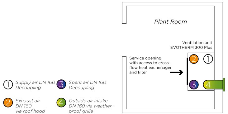
The following points should be considered when choosing the position of the ventilation unit:
- Good access to the device for maintenance such as changing filters or unscheduled repairs.
- The installation location should be in a frost free temperature zone. This will ensure that the condensate pipe will not be frozen and the heat loss through the device housing and ducting will be minimized.
- To prevent structure-borne noise the device should be installed with vibration cushions and acoustically decoupled from the air transmission system. This can be achieved with canvas connectors in the exit connections.
- It is essential that the device is installed in a horizontal alignment to prevent condensate leaking from the condensate tray into the workings of the device.
- The device may not be installed in an environment with strong smells.